I’ve been trying to optimize performance of my new upcoming Mic Preamp Kit, the NK-72DI. It’s hooked up on my workbench to various probes and meters, and displays. I want to make sure that performance of this new Mic Preamp will be top-notch, and something my customers will be proud of building, owning and using!
Yes, the cost of the kit may be “inexpensive” compared to buying other commercially ready-made Mic Preamp modules out there, but don’t let the price fool you… this is not a “cheap performing” preamp. I want performance of this preamp to be on same level or more, as the other more well-known, and expensive brands out there.
As I mentioned in an earlier post, this new Mic Preamp uses discrete Op Amp to amplify the minute microphone level signal and drive the output transformer. One can also use off-the-shelf PDIP IC chips, plugged into one of our “Hybrid Discrete OpAmp” Board Adapter. This allows you to use commercially available 8-pin IC chip, and boost it’s output current drive capability to make sure it can handle our large output transformer. (I’ll talk more about this “Hybrid Discrete OpAmp” on a later post, so please subscribe or follow us on Facebook.)
Okay, so this is a photo of our NK-72DI Mic Preamp prototype, hooked up to our 4-channel Digital Storage Oscilloscope.
We’re monitoring basically the Input Signal being fed to the Mic Preamp for use as our “reference” signal, the resulting signal at the secondary side of the Input Transformer, the amplified signal after the Discrete OpAmp, and the resulting output signal after the Output Transformer. So it’s basically our complete signal path, from input to output, and all points in-between. We’re feeding the Mic Preamp a Square Wave signal, coming from our multifunction generator, and hooked up to an HP Frequency Counter. 
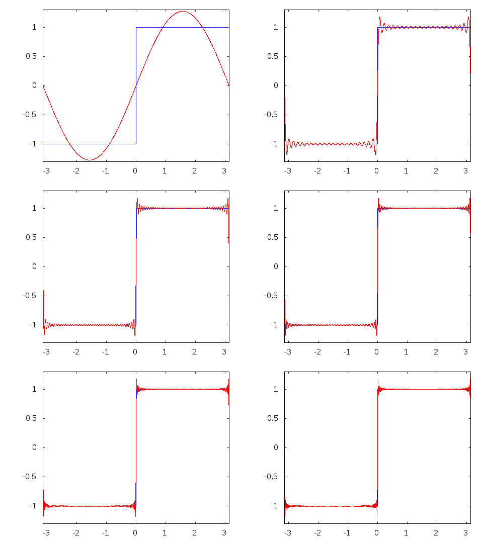
The reason we’re using a Square Wave for testing is because the “ideal” Square Wave is composed of an infinite sum of sine waves of different frequencies. (A sine wave on the other hand is just one fundamental pure frequency.) A square wave has a single fundamental frequency, plus all it’s odd harmonics; where the amplitude (or signal level) of each odd harmonic is 1/n.
In mathemical terms, it’s described as:

An animation of how multiple odd harmonics added to the fundamental frequency results in a square wave:

Credits: Wikipedia.org
During the course of testing, I noticed an “overshoot” on our signal waveform.
As you can see from the CYAN trace (secondaries of Input Transformer), there is a slight peak at the start of the square wave, an “overshoot.”
Which is then further amplified by our Discrete OpAmp as this signal travels forward through our system, as can be seen from the PURPLE trace.
This “overshoot” is not present in our input reference signal (YELLOW trace), so this anomaly only starts to manifest after our Input Transformer. Surely, one of the component value I’ve used in this initial prototype is not optimal.
We basically need to find the right amount of “loading” for our Input Transformer to get rid of this “overshoot”, sort of dampening the signal. One can desolder/solder different resistor values to the prototype board, but that is tedious and messy work. Instead, I used a DIY custom-made resistor substitution box made from “thumbwheel” switches.
Each digit position is composed on 10 tiny SMT (Surface Mount Technology) resistors wired in series and tapped at each junction. So for the “ones” position, we have 1-ohm resistors. For the “tens” position, we have 10-ohm resistors, and for the “hundreds” position, we have 100-ohm resistors in used, and so on.
So if we dial a numerical value on the substitution box, of say “12345”, we’re effectively setting a resistance of 12,345 ohms. Easy-peasy!
We hooked the above resistor substitution box in parallel with an existing resistor on the prototype, and proceed to adjust the values by pressing the [+] or [-] switches to change the digits and watching the resulting waveform on the scope. A fter we’ve dialed the optimum value, the “overshoots” on our waveform disappeared, and we’re presented with a nice square looking waveform!
A screen capture of the scope display confirms it too in more detail.
The BLUE waveform, is the final output after the Output Transformer. Overshoot removed, we now have a clean and nice looking square waveform. Now, you may have notice the final Output Waveform doesn’t have a steep and sharp pointed corners as compared to our Input Waveform. What’s going on? That is the result of a slight HF rolloff imparted by the Output Transformer, and to a lesser extent, also by the Input Transformer. That is basically our Input and Output Transformers imparting it’s sonic signature to our input signal. You can say these transformers “smoothen out” the edges, smooths out the high frequency response, while keeping the low-end frequencies fat and beefy. A transformer-less preamp design, like our SK-1DI Mic Preamp, will not have this effect, and will attempt to reproduce the input signal as faithful as possible. Thus, we describe the SK-1DI Mic Preamp as being a “fast” preamp, so you can get a more “transparent” sound.


